Practical depth guide
Depth map vs height map: same grayscale, different promise
Both may look like black-to-white images. A depth map describes distance from a viewpoint; a height map describes elevation from a reference surface. Confusing the two can make an apparently valid file fail in the next tool.
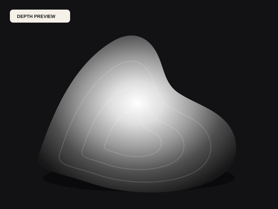
A depth map belongs to a camera view
Each depth pixel corresponds to a pixel in the source view and estimates how far the visible surface is from the camera. Change the camera and the map changes because new surfaces appear, occlusions move, and distance relationships shift. Monocular AI usually returns relative or scale-ambiguous depth unless the model and calibration explicitly support metric output.
Depth maps are useful for depth of field, atmospheric effects, masks, parallax, view-conditioned reconstruction, and as a starting field for front-facing relief. They naturally encode the visible scene, including background distance. That same background can be undesirable when the goal is a shallow plaque, which is why range remapping and cropping are important.
A height map belongs to a surface or world plane
A height map assigns elevation above or below a reference plane. Terrain height maps may carry real geographic elevation and coordinates. PBR and displacement height maps describe surface relief in texture space. CNC height fields describe the shape to manufacture. None of those meanings requires a camera, although an image-derived field may be projected onto a plane.
A valid height map should match the downstream scale and boundary assumptions. A terrain generator needs geographic data, not estimated photographic depth. A tileable material needs edge continuity. A relief needs a stable base and manufacturable slope. Simply renaming a depth PNG does not meet those contracts, but remapping and constraining the field can make it a useful starting point.
Convert by defining the new reference
To use depth as relief height, first decide which visible surface becomes the low plane. Crop or flatten the background, set the useful near and far range, choose inversion, and map normalized values to a physical relief height. Add side walls and a bottom when a solid mesh is required. This creates a 2.5D object tied to the original view, not a complete sculpture.
To create PBR displacement, decide how the texture coordinates, neutral level, amplitude, and edges work. To create terrain, obtain a digital elevation source with the required projection and resolution. These are product decisions, not encoding tricks. A 16-bit file can carry the result more smoothly, but it does not decide what the values mean.
Choose the page that matches the actual job
Use the depth map generator when the source is a photo and the immediate need is camera-relative scene structure. Use the image-to-height-map page when the target is relief or displacement and you understand that the field is image-derived. Use a GIS heightmap tool for real-world terrain. Use the normal-map generator when the target needs surface orientation rather than distance or elevation.
Write the meaning beside the file: near-is-white or far-is-white, normalized or metric, camera-relative or surface-relative, dimensions, bit depth, and coordinate convention. This small record prevents a later team member from inferring the wrong contract based on a grayscale thumbnail. It also makes tests reproducible across tools and versions.
Before the file moves forward
Final checklist
- The file's values are defined as camera distance or surface elevation.
- Relative, normalized, or metric scale is stated explicitly.
- Near/high direction and neutral level are documented.
- The target needs photo depth, relief, PBR displacement, or true terrain data.
- Boundaries, aspect ratio, and coordinate convention match the receiver.
- Conversion decisions are recorded with the project file.