01
CNC job shops
Quote and approve relief work with a visible, dimensioned intermediate file.
3D relief software for CNC
Convert client artwork into controlled depth and closed geometry, then move it into the CAM software you already trust. Preview and remap the relief before a blank, spindle hour, or delivery date is at risk.
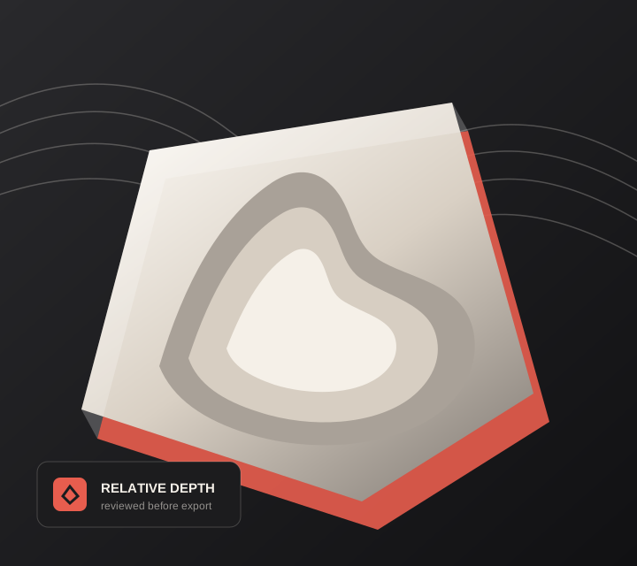
Live manufacturing workbench
Three free AI previews per day. Source checks, editing, 3D preview, and compatibility exports are free.
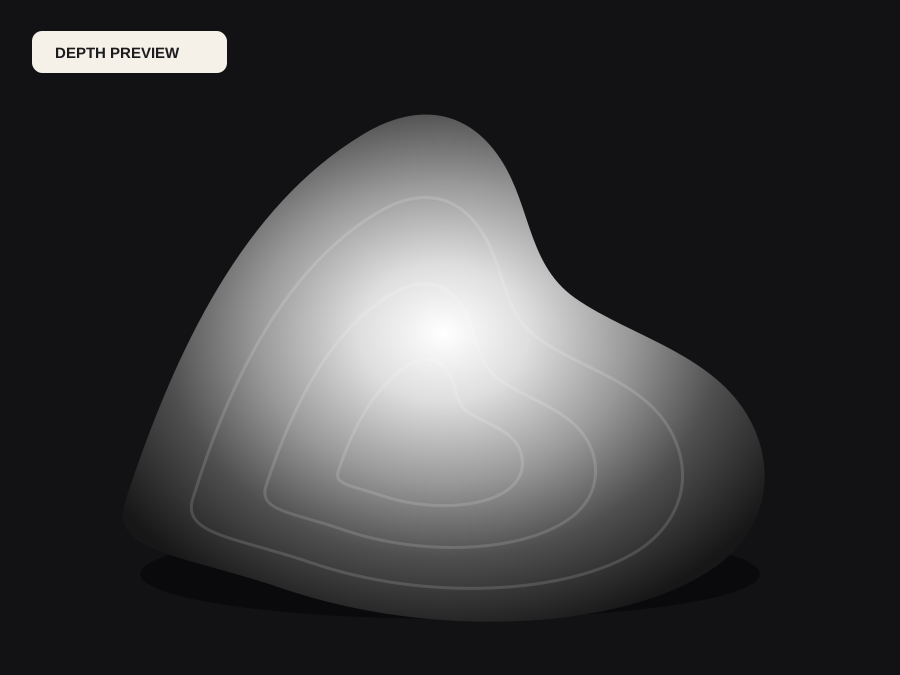
Choose a source image to begin.
Real work, real failure cost
The useful product is not the model call. It is the review loop that catches a reversed field, a noisy border, or an impossible relief before the next tool turns that mistake into wasted time.
01
Quote and approve relief work with a visible, dimensioned intermediate file.
02
Fit shallow carved detail within known stock thickness and finishing plans.
03
Ship consistent STL assets that open cleanly in common CAM packages.
01
A compelling grayscale image can still produce a poor toolpath. Tiny halos turn into ridges, noisy backgrounds waste cycle time, and steep jumps demand cutters that cannot reach the detail. DepthCarve lets you inspect the estimated field beside the source, compress irrelevant distance, flatten low-value regions with range controls, and decide whether the source is suitable before exporting geometry.
The STL carries millimeter dimensions and a solid backing, making it easier to place against stock in Aspire, Carveco, Fusion, Vectric workflows, or another CAM system. It does not know your workholding, bit length, spindle limits, or material behavior. Those constraints remain in CAM, where simulation and machine-specific post-processing belong.
02
Relief height should be chosen with the smallest planned finishing tool in mind. A tall change across a short pixel distance creates a steep wall, and the cutter may rub, leave uncut material, or lose detail. Lowering total relief height often improves the result more than increasing mesh density. Use contrast to separate meaningful planes, but avoid turning soft features into cliffs.
Grid size controls triangles, not artistic fidelity. Start with a moderate grid, generate roughing and finishing simulations, and inspect remaining stock. Increase the grid only when toolpaths reveal faceting that the source depth genuinely supports. A dense noisy mesh produces longer calculations and more machine motion without guaranteeing a smoother carved surface.
03
Crop and clean the artwork first. Generate a free map, verify whether light or dark should become the raised region, and adjust the useful range. Export a test STL at the final aspect ratio, import it at a known origin, and confirm dimensions. Then create roughing and finishing operations with safe stock allowance, boundary offsets, and a material-appropriate step-over.
Run CAM simulation and check the deepest point against the real blank, spoilboard, and fixturing. For a new source style or material, cut a small sample before the final piece. This staged loop is slower than one-click G-code but dramatically cheaper than discovering a reversed portrait or unreachable crevice halfway through a customer job.
04
Free source checks, shaping, 3D preview, manufacturing checks, compatibility PNG, and preview STL make quoting and source rejection inexpensive. One approved production job costs one credit and delivers every standard output together. The same source job is idempotent, so rebuilding available files after parameter changes does not repeatedly debit the ledger.
Approved production jobs reserve one credit before the provider call and refund the original debit automatically on failure. The application records status, fingerprints, and accounting entries without storing the customer image in D1. Output links remain temporary, so the verified ZIP belongs in the shop's normal project and backup process immediately.
Five bounded stages
Check source contrast, edge detail, border clutter, and resolution before an AI call is trusted.
Adjust the subject mask, background, curve, detail, smoothing, taper, frame, and real dimensions for free.
Compare beam or tool size, tonal slices, slope, base, manifold topology, and bounding box with the real setup.
Approve one successful production job only after the free 2D and 3D previews earn acceptance.
Download one verified ZIP and inspect it in LightBurn, CAM, or a slicer before committing production material.
Choose by next action
| Output | Use it for | It does not guarantee | Cost |
|---|---|---|---|
| 8-bit PNG | Preview, mask, laser and compositing tests | Physical scale or machine settings | Free |
| Compatible 16-bit PNG | Compatibility with grayscale depth workflows | Additional source precision | Free |
| Preview STL | Low-cost scale and import checks | Printability, tool reach, or safe G-code | Free |
| Production job bundle | Raw EXR, true 16-bit pair, STL, preview and manifest | Hidden surfaces or certified metric truth | 1 credit |
Straight answers
Any CAM package with standard STL import may work, including common Aspire, Carveco, Fusion, and Vectric workflows. Confirm scale, units, normals, and boundaries after import.
No. Those values depend on the cutter, machine, material, workholding, and spindle. Configure and simulate them in your CAM software.
Use PNG when your software creates relief from brightness. Use STL when you want DepthCarve to create the closed geometry and your CAM package accepts meshes.
The Production plan includes API access for automated depth maps. Review and CAM setup should still be tied to each order's material and dimensions.
Preview the idea. Pay for usable output.
Start without an account. When a professional format earns approval, use the welcome credit or choose a pack that matches the shop's workload.