01
Router owners
Make shallow decorative reliefs without hand-sculpting every field.
Depth map for CNC
Prepare brightness as intentional relief height, not accidental photographic luminance. Export a reviewed map or closed mesh, then simulate it with real stock and cutters.
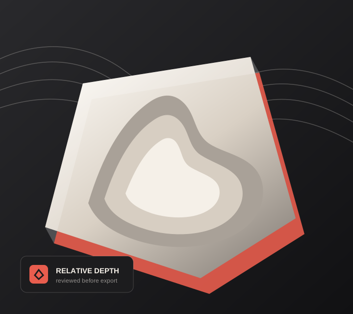
Live manufacturing workbench
Three free AI previews per day. Source checks, editing, 3D preview, and compatibility exports are free.
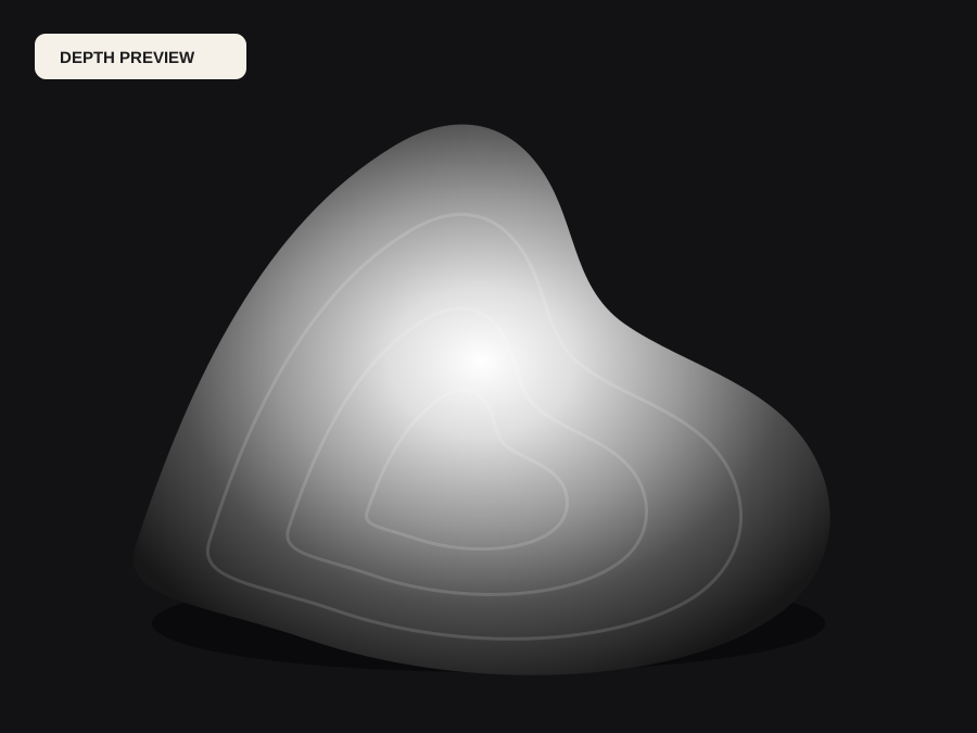
Choose a source image to begin.
Real work, real failure cost
The useful product is not the model call. It is the review loop that catches a reversed field, a noisy border, or an impossible relief before the next tool turns that mistake into wasted time.
01
Make shallow decorative reliefs without hand-sculpting every field.
02
Protect valuable blanks with an approval-first workflow.
03
Receive predictable input and preserve machine decisions in CAM.
01
A depth map for CNC states intended height across an area. Turning that into motion requires a cutter with a real radius, a machine with real acceleration, and stock that behaves. A field with a near-vertical step is geometrically valid and machinable only if the tool can reach it, which is why smooth, bounded transitions are usually worth more than dramatic contrast.
The practical consequence is that the depth map should be judged on slope and reachability, not only on how recognisable the subject is. Steep walls, thin ridges, and deep narrow valleys are the features that break a job after the design has already been approved.
02
A ball-nose cutter leaves a scalloped surface whose depth depends on stepover and diameter; a V-bit resolves points but flattens everything else; a small flat end mill needs clearance that a facial relief rarely has. Those constraints set how much relief the piece can carry before detail becomes unreachable or fragile.
Review the beam-or-tool comparison and the slope report before approving. They are cheap checks against real tool dimensions, and they answer the question a rendering cannot: whether the shape you designed is one this cutter can produce.
03
Maximum relief depth has to fit inside the stock after surfacing, and thin borders have to survive workholding. Neither is visible in an image, and both are common causes of a ruined blank on an otherwise correct file.
Run the project in the CAM package's simulation with real stock and the actual tool before cutting. Then check origin, units, and post-processor. The exported PNG or STL is prepared geometry: it carries no speeds, feeds, or machine safety, and it is never G-code.
Five bounded stages
Check source contrast, edge detail, border clutter, and resolution before an AI call is trusted.
Adjust the subject mask, background, curve, detail, smoothing, taper, frame, and real dimensions for free.
Compare beam or tool size, tonal slices, slope, base, manifold topology, and bounding box with the real setup.
Approve one successful production job only after the free 2D and 3D previews earn acceptance.
Download one verified ZIP and inspect it in LightBurn, CAM, or a slicer before committing production material.
Choose by next action
| Output | Use it for | It does not guarantee | Cost |
|---|---|---|---|
| 8-bit PNG | Preview, mask, laser and compositing tests | Physical scale or machine settings | Free |
| Compatible 16-bit PNG | Compatibility with grayscale depth workflows | Additional source precision | Free |
| Preview STL | Low-cost scale and import checks | Printability, tool reach, or safe G-code | Free |
| Production job bundle | Raw EXR, true 16-bit pair, STL, preview and manifest | Hidden surfaces or certified metric truth | 1 credit |
Straight answers
Use PNG if the CAM package builds relief from grayscale. Use STL when mesh import is reliable and you want an explicit closed object. The best choice depends on the installed software and shop workflow.
As deep as the tool can reach and the stock can give up. Check maximum depth against remaining stock thickness, and keep the relief shallow enough that the smallest features stay machinable.
A ball nose for the bulk of the form, because it leaves predictable scallops that finishing passes can reduce. Use a V-bit for fine lines and lettering where sharpness matters more than surface finish.
Units, origin, maximum depth, workholding, tool length and clearance, stock allowance, and the simulation. Confirm the post-processor matches the machine controller before the first cut.
Preview the idea. Pay for usable output.
Start without an account. When a professional format earns approval, use the welcome credit or choose a pack that matches the shop's workload.