01
Aspire users
Reduce background cleanup and reversed relief after import.
Aspire depth map
Create and remap relative depth outside the CAM project, then import a reviewed grayscale field or closed STL at known dimensions.
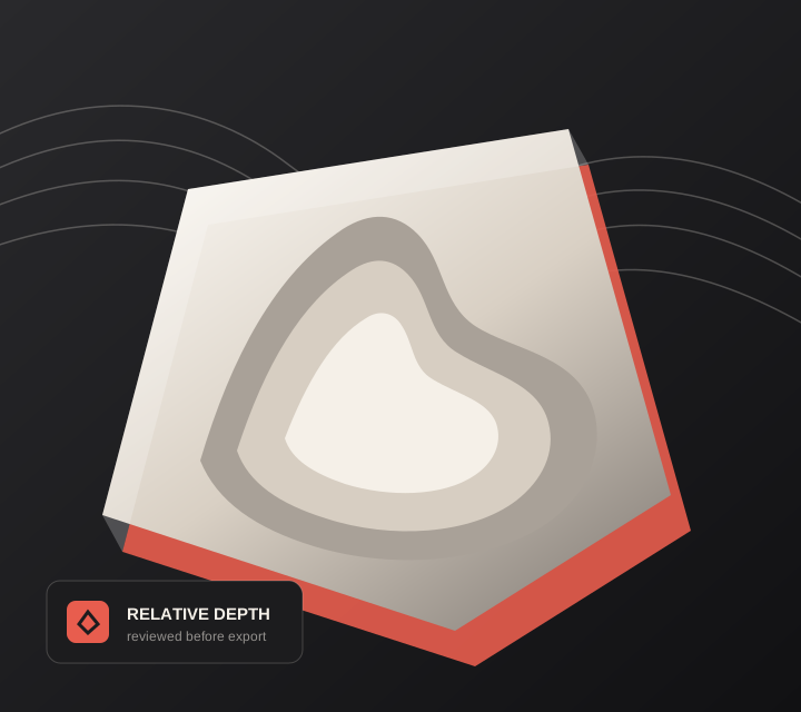
Live manufacturing workbench
Three free AI previews per day. Source checks, editing, 3D preview, and compatibility exports are free.
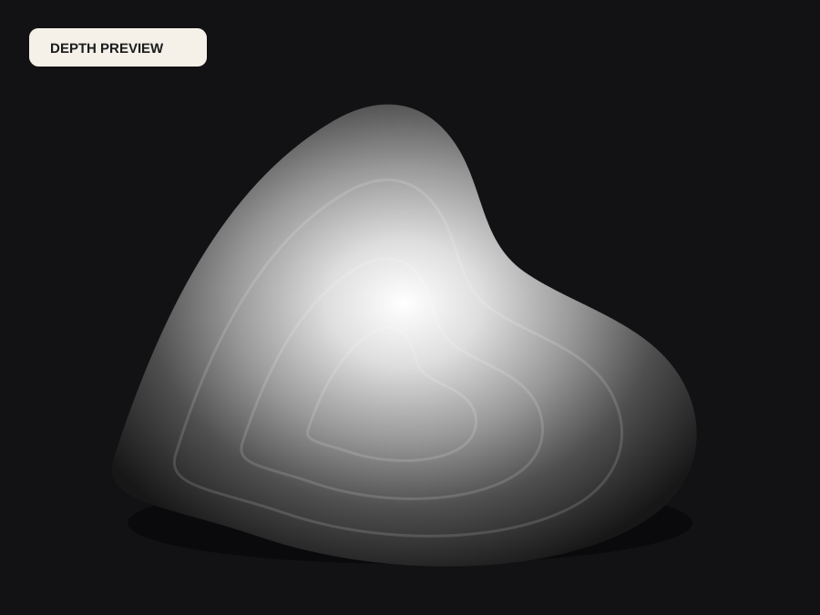
Choose a source image to begin.
Real work, real failure cost
The useful product is not the model call. It is the review loop that catches a reversed field, a noisy border, or an impossible relief before the next tool turns that mistake into wasted time.
01
Reduce background cleanup and reversed relief after import.
02
Standardize customer-image preparation before CAM.
03
Separate depth concepts from toolpath and machine safety lessons.
01
Aspire builds relief from a grayscale value mapping, so anything in the file becomes part of the model. Background clutter that would have been trimmed elsewhere arrives as a low-amplitude texture across the whole component, and a reversed field produces a plausible shell that machines inside out.
Doing the range work first keeps the CAM project clean: flatten the background, set a deliberate low plane, confirm inversion against the intended cutting direction, and save the adjusted PNG beside the Aspire file so the mapping behind a finished component is still recoverable months later.
02
A relief that meets a flat background needs a border that is genuinely flat. Setting one before import is far cheaper than editing the component afterwards, and it gives the boundary a predictable height to blend into rather than a ragged edge that has to be sculpted away.
Width and height only mean something together. Record the intended physical width and decide the component height from the finishing tool and the stock, then reuse the same range across an order so two plaques cut on different days still match. Consistency across a run is usually worth more than one component being individually optimal.
03
Import behaviour differs between Aspire versions and between the PNG and STL routes. Units, component height, combine mode, zero plane handling, and boundary behaviour all live inside the installed software, and they must be confirmed there rather than assumed from a tutorial written for a different release.
The same applies to toolpaths. DepthCarve does not choose cutters, stepover, feeds, or post-processors, and it does not claim that a depth file is machine instruction. Simulate with real stock and the actual tool before anything touches material.
Five bounded stages
Check source contrast, edge detail, border clutter, and resolution before an AI call is trusted.
Adjust the subject mask, background, curve, detail, smoothing, taper, frame, and real dimensions for free.
Compare beam or tool size, tonal slices, slope, base, manifold topology, and bounding box with the real setup.
Approve one successful production job only after the free 2D and 3D previews earn acceptance.
Download one verified ZIP and inspect it in LightBurn, CAM, or a slicer before committing production material.
Choose by next action
| Output | Use it for | It does not guarantee | Cost |
|---|---|---|---|
| 8-bit PNG | Preview, mask, laser and compositing tests | Physical scale or machine settings | Free |
| Compatible 16-bit PNG | Compatibility with grayscale depth workflows | Additional source precision | Free |
| Preview STL | Low-cost scale and import checks | Printability, tool reach, or safe G-code | Free |
| Production job bundle | Raw EXR, true 16-bit pair, STL, preview and manifest | Hidden surfaces or certified metric truth | 1 credit |
Straight answers
Use PNG when you want Aspire to build the relief from grayscale. Use STL when you want to import the already closed, dimensioned mesh. Compare both on a small project if the workflow is new.
The grayscale direction disagrees with the direction Aspire expects for that operation. Invert the range before import, or flip the component height, and confirm against the preview before cutting.
Enough for the smallest finishing tool to resolve, and no more. Deep components increase machining time and exaggerate estimator noise. Increase the physical width before increasing the height.
No. The PNG and STL carry geometry and grayscale values only. Speeds, feeds, stepover, tool selection, and post-processing are decided in Aspire for your machine and material.
Preview the idea. Pay for usable output.
Start without an account. When a professional format earns approval, use the welcome credit or choose a pack that matches the shop's workload.