Practical depth guide
How to read and repair a grayscale depth map
Grayscale is only an encoding. You still need to know which end is near, what the range means, where the model failed, and how the next application turns values into an effect or physical surface.
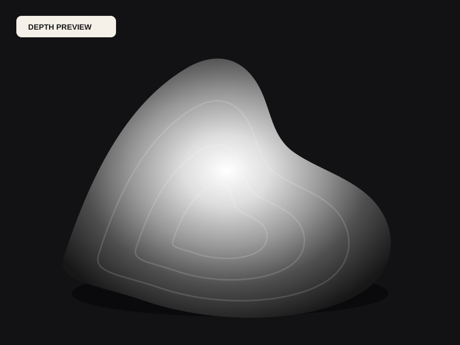
Define black and white before editing
There is no universal rule that white must be near. Many visualization examples use white for closer surfaces, while displacement and machine workflows may use white for higher elevation. Some software offers an inversion switch and some silently assumes one convention. Use a simple wedge or known object to verify the receiver instead of depending on memory.
Write the chosen convention with the file. For relative depth, values describe ordering and normalized distance rather than meters. For relief, the same values may be remapped to millimeters. The visual image can appear plausible under either inversion, so correctness comes from the contract, not the thumbnail.
Use the histogram range without crushing structure
When a few extreme pixels occupy black and white, most of the subject can collapse into middle gray. Move black and white points inward to allocate more levels to the useful object. Watch eyes, edges, hair, and shallow curves for clipping. Increased contrast can improve separation, but it can also exaggerate a model error into an unmanufacturable step.
A flat background is helpful for many reliefs because it defines a consistent base. It is not always helpful for VFX, where background distance drives fog or depth blur. Edit around the final intent. Keep an unmodified model output so a destructive grade can be compared and reversed.
Recognize halos, islands, bands, and false texture
A halo is a light or dark outline that does not belong to the object's actual shape. In a relief it becomes a trench or ridge; in compositing it creates an obvious fringe. Islands are isolated values that become spikes or holes. Bands indicate quantization or over-aggressive range expansion. False texture appears when shadows, print, or surface color are interpreted as geometry.
Range controls can suppress small problems but cannot reorder an incorrectly understood scene. Crop, choose a clearer source, retouch the field, or use a specialized segmentation step. Increasing resolution or converting to 16-bit will make a structural error denser, not more accurate.
Test the grayscale path end to end
Download the free 8-bit PNG and import it into the actual target. Confirm aspect ratio, direction, color management, and whether the software treats it as grayscale or converts it. For 16-bit workflows, inspect metadata and check that the receiving application preserves the wider samples. For relief, render under grazing light or build a low-density mesh to expose abrupt slopes.
For a laser or CNC job, keep machine settings out of the image contract. Test the field on scrap with documented material and tool parameters. For VFX, check the pass under the intended blur, fog, and parallax amplitude. A map that looks smooth by itself can fail when the downstream effect magnifies a small edge error.
Before the file moves forward
Final checklist
- Near and far direction is confirmed in the receiving tool.
- Relative or metric interpretation is documented.
- The useful subject occupies enough of the grayscale range.
- Halos, isolated islands, and false texture are inspected at full size.
- Bit depth and channel count survive the import path.
- The final effect or physical process is tested at low cost.