Practical depth guide
Depth maps for laser engraving that survive the controller
A grayscale file can look right and burn wrong. This guide connects the estimated depth field to the three things that decide the result: direction, usable range, and the machine's own grayscale interpretation.
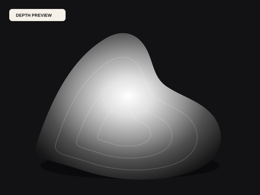
Decide what brightness must mean on your machine
Different controllers and engraving modes treat darker pixels as deeper passes, more power, or slower travel. Some offer an inversion switch and some do not. Before touching the range controls, confirm with a two-tone test whether black or white produces the deeper burn on the target material and mode. Write that decision beside the file; a map prepared for one machine can be silently wrong on another.
The depth estimate from a photo is relative scene depth, not a material removal plan. It becomes an engraving input only after you decide which structures matter and how the controller reads them. A flat, quiet background is usually desirable, but a light engraving style may keep background texture on purpose. Make the convention explicit before editing.
Squeeze the useful range without creating banding
When the interesting subject occupies a narrow band of grayscale, move the black and white points inward so more of the output range describes the part that will be burned. Contrast then separates nearby levels. Pushing too far creates visible contour bands, which the laser will reproduce faithfully. Watch faces, sky gradients, and shallow curves: these show banding first and produce stippled or terraced engraving when the image path is too aggressive.
An 8-bit PNG provides 256 levels, which many laser workflows can reproduce well. A 16-bit grayscale container avoids banding across long gradients only when the source computation and the controller both preserve it; many laser drivers convert the file internally. The free compatible 16-bit export from DepthCarve is honestly labeled as preview-derived, so treat it as a compatibility option rather than added precision.
Dithering, noise, and the stippling trade-off
Some controllers apply their own dithering to simulate shade. If the source map already contains estimation noise, dithering can amplify it into a speckled field, especially on coated materials. Smoothing the depth field in the workbench, flattening the background, and keeping fine texture out of large flat regions all reduce unwanted stippling without hiding real detail.
If the engraving style intentionally needs stipple, control it in the laser software rather than baking noise into the map. A clean grayscale file gives the operator room to choose dither patterns, line intervals, and overscan. A noisy file removes that choice before the job starts.
Test the exact path, then scale
Generate a small calibration strip with the same material, coating, lens focus, speed, power, line interval, and controller mode as the final piece. Compare the burned result against the on-screen map at the intended size. Small feature loss, blurred boundaries, or an unexpected inversion become visible here for the cost of scrap instead of a finished product.
Import the free PNG into the actual laser software and confirm the preview, the assumed direction, and the size before approving anything paid. The machine parameters belong to the operator and the material; no image preparation can safely replace that calibration. A well-prepared depth map makes the test decisive instead of ambiguous.
Before the file moves forward
Final checklist
- The controller's black-or-white direction is confirmed with a two-tone test.
- The useful subject occupies the grayscale range without visible banding.
- Background noise is flattened and fine texture is controlled deliberately.
- The chosen bit depth matches what the laser software actually preserves.
- A calibration strip on the real material matches the on-screen preview.
- Machine settings stay separate from the prepared grayscale file.