Practical depth guide
Convert a depth map to STL without creating an open shell
A depth image becomes useful geometry only after its pixels are sampled, scaled, connected, and closed. Understand each step before a technically valid mesh reaches a slicer or CAM project.
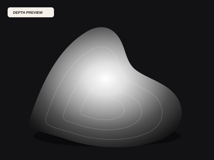
Map pixels into physical coordinates
Each grayscale sample becomes a vertex height. Image X and Y map to the chosen physical width and its aspect-ratio-derived height. The normalized depth value maps to base thickness plus a selected relief height. This makes the scale explicit instead of leaving downstream software to guess whether one unit means a millimeter, inch, or meter.
DepthCarve samples the field to a bounded grid. More samples create more triangles and can follow finer changes, but they also preserve noise and increase memory, download size, slicing time, and CAM calculation. Begin with a moderate grid and increase only when the final physical process can reproduce the additional detail.
Close the top with walls and a bottom
A height surface alone has no volume. DepthCarve triangulates each grid cell into a top, walks the four perimeter edges to create side walls, and adds two triangles for a flat bottom. The complete binary STL is therefore a backed relief rather than a floating sheet. The exporter checks its predicted and written triangle counts and fails loudly if construction is inconsistent.
Watertight means the mesh encloses volume. It does not mean every normal, feature, overhang, or slope suits the target process. Slicers may still flag very thin features. CAM software may find steep regions unreachable. A mesh validator and the target application's own simulation remain part of the contract.
Choose height and base for the manufacturing method
Relief height controls the total raised range, not stock thickness. For CNC, choose it around cutter diameter, tip geometry, reach, and desired finishing time. For FDM, compare it with nozzle width and layer height. For resin, consider supports, suction, and fragile peaks. Tall relief in a small width creates steep walls and is often less readable than a restrained, well-graded surface.
Base thickness gives the object strength and a predictable flat reference. A plaque that will be screwed, glued, framed, or machined from stock needs different backing. DepthCarve enforces a minimum but cannot choose the correct engineering dimension. Include mounting, finishing, and remaining stock in the decision.
Inspect, slice or simulate, then test
Open the STL in a mesh viewer and verify bounding dimensions, orientation, the lowest plane, and the highest point. Look along the silhouette for walls and under the model for the bottom. In a slicer, inspect every layer around fine islands. In CAM, confirm units, stock, origin, safe Z, boundaries, roughing allowance, finishing toolpath, and remaining material.
Do not generate unreviewed G-code from a generic web tool. Machine-specific post-processors, workholding, cutter data, and controller limits are safety-critical. Use the DepthCarve STL as a bounded geometry handoff, then let verified downstream software perform the operation it was designed to control.
Before the file moves forward
Final checklist
- The depth field has the correct direction and a quiet intended base.
- Width, aspect ratio, relief height, and base thickness are intentional.
- Mesh grid matches real process resolution rather than maximum file size.
- The STL opens as a closed volume with correct dimensions and orientation.
- Slicer or CAM simulation exposes no unsupported or unreachable features.
- A low-cost physical test is completed before final production.