Practical depth guide
Depth map vs normal map: distance values or surface direction
Short answer: a depth map stores one value per pixel, how near or far that point is, so it can be turned into relief height, a mesh, or a focus mask. A normal map stores a direction per pixel, which way the surface faces, so a renderer can fake small bumps under light. Pick depth when something must be cut, printed, displaced, or composited by distance; pick normals when a flat polygon only needs to look detailed. Many projects need both, and they agree best when they come from the same estimate.
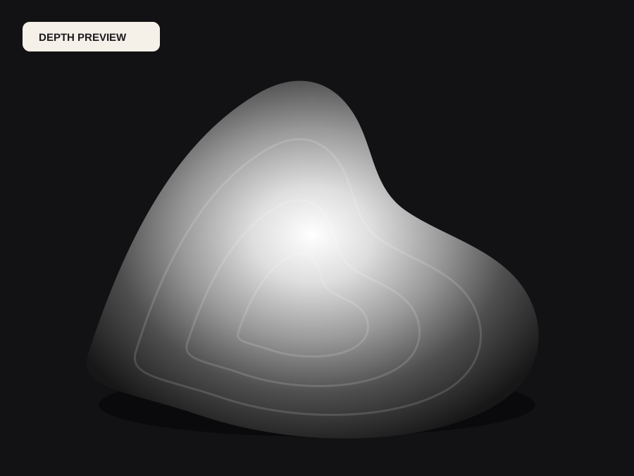
What a depth map actually stores
A depth map is a single-channel image. Every pixel holds one number that describes how far the visible surface is from the camera, usually displayed as grayscale where one end means near and the other means far. Because it is one scalar per pixel, it can be read directly as a height field: map black to the lowest plane, map white to the tallest point, multiply by a physical relief height, and you have geometry. That is exactly what CNC carving software, laser engravers that burn by intensity, and STL relief generators consume.
An AI depth map made from one photograph is relative, not measured. It knows that the nose is in front of the cheek and the cheek is in front of the wall, but it does not know that the nose is 18 millimetres proud of the face unless a calibrated model says so. For relief work that is usually fine, because you choose the final height yourself. For measurement, you need a calibrated sensor, photogrammetry, or a model that explicitly outputs metric depth.
What a normal map actually stores
A normal map uses three channels to store a direction vector for each pixel. Red, green, and blue encode the X, Y, and Z components of the way the surface faces, which is why a typical tangent-space normal map looks mostly lavender: flat areas point straight out of the surface and encode as roughly (0.5, 0.5, 1.0). A shader reads those vectors and lights each pixel as if the surface were tilted, so a flat plane can look bricked, scratched, or embossed without adding a single polygon.
A normal map does not say how high anything is. Two surfaces with the same slope but different heights produce the same normals, and a deep cliff and a shallow step can look identical in the map. That is why you cannot carve a normal map on a CNC router or print it as a relief directly: integrating directions back into height accumulates error, and anything hidden from the light direction is ambiguous. Normals are a shading input, not a manufacturing input.
Which one your workflow needs
Choose a depth map for CNC relief carving in Aspire, Carveco, or Fusion, for 3D printed lithophanes and plaques, for laser engraving with grayscale power, for converting a photo to an STL, for depth of field and fog in compositing, for parallax and 2.5D camera moves, and for ControlNet-style conditioning where the model expects distance. In all of these the downstream tool needs to know where material, focus, or space begins and ends, and only a scalar distance or height can tell it.
Choose a normal map for real-time game assets, product renders, and look-development where detail must react to moving light but the silhouette stays the same. Normal maps are cheap at render time and they hold fine surface variation that would be expensive as geometry. If you are texturing in a PBR pipeline, you will often want a height or displacement map for parallax plus a normal map for lighting, which is a strong hint that the two maps complement rather than replace each other.
Converting between them and where it breaks
Going from depth to normals is straightforward: take the gradient of the depth field in X and Y, build a vector from the slopes, and normalize it. Most texture tools do this, and the result is only as clean as the depth it came from. Noise in the depth becomes speckled lighting, and a hard step in depth becomes a bright or dark seam. Smoothing the depth slightly before deriving normals usually helps more than sharpening the normals afterwards.
Going from normals back to depth is the fragile direction. Integration needs a starting height, assumes the surface is continuous, and spreads any error across the whole image, so cliffs flatten and separate objects melt into one another. If you only have a photograph, it is more reliable to estimate depth from the image first and derive normals from that estimate. Then a crease in the normal map sits exactly where the step is in the depth map, and a shading artifact can be traced to one source instead of two disagreeing tools.
Making both from one photo with DepthCarve
Upload a photo to the free depth map generator on the DepthCarve homepage and you get a relative depth preview with black point, white point, contrast, and invert controls, plus a free 8-bit PNG and a preview STL. That covers the depth side of most relief, laser, and compositing tests without an account. When the job needs surface orientation, the image to normal map page runs the same photo through the geometry provider so the normals and the depth come from one estimate rather than from two unrelated preprocessors.
The approved production job costs one credit and returns a bundle: raw floating-point depth, verified true 16-bit forward and inverse PNGs, a watertight STL, and a parameter manifest, with provider normals, a point cloud, GLB, and camera data recorded when the provider supplies them. Provider links are temporary, roughly an hour, so download the ZIP straight into the project archive. Before shading, check the normal map against a lit sphere for channel order, OpenGL or DirectX green, and camera versus tangent space.
Common mistakes when choosing between them
The first mistake is sending a normal map to a carving or printing tool because it looks detailed. The tool will read the red, green, or luminance channel as height and carve a tinted image instead of a shape. The second is expecting a depth map to show fine texture under light. A depth map with fabric weave or skin pores baked into it will carve noise; detail that only matters for shading belongs in the normal map, while depth should describe the broad form.
The third mistake is mixing conventions silently. Depth can be white-near or white-far, and normals can use an inverted green channel. Decide the convention once, write it down, and test a tiny sample in the real software before committing material or a long render. The parameter manifest in the DepthCarve production bundle exists for exactly this reason: the next revision should not depend on someone remembering which way the map was flipped.
Before the file moves forward
Final checklist
- You know whether the next tool needs height or distance (depth) or surface direction (normals).
- Physical outputs such as CNC, laser, lithophane, and STL use depth or height, never a normal map.
- Normals are derived from the same depth estimate so seams line up.
- Depth direction, white near or white far, is confirmed in the receiving software.
- Normal channel convention and space are checked on a lit sphere before shading.
- A small, cheap test runs in the real tool before material or render time is committed.