01
Commission artists
Create approval renders and files from customer photos.
Image to 3D relief
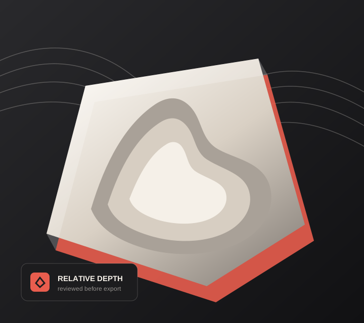
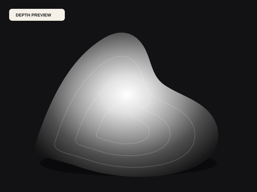
Use estimated scene structure as a starting field, compress it into a practical relief height, and generate backed geometry rather than a fragile open surface.
Live manufacturing workbench
Three free AI previews per day. Source checks, editing, 3D preview, and compatibility exports are free.
Choose a source image to begin.
Real work, real failure cost
The useful product is not the model call. It is the review loop that catches a reversed field, a noisy border, or an impossible relief before the next tool turns that mistake into wasted time.
01
Create approval renders and files from customer photos.
02
Move from picture to closed mesh before CAM.
03
Generate flat-backed objects for slicing and listing previews.
01
Estimating scene distance is the easy half. A full-scene depth field spreads its range across whatever the camera saw, including sky, floor, and background furniture, so the subject ends up occupying a thin band of the available height. Converting an image to 3D relief means deciding how much of that band the subject deserves and what happens to everything behind it.
DepthCarve exposes that decision directly: black and white points to discard dead range, gamma and contrast to redistribute it, background flattening to pin distant scenery to a low plane, and a taper to keep the edge from becoming a vertical wall. Those controls act on the estimate, so exploring them costs nothing after the initial preview.
02
A relief STL from a displacement export is often a zero-thickness sheet. Slicers and CAM packages disagree about what that means, and the result ranges from a mesh that needs extensive repair to one that silently slices as a single layer. DepthCarve builds the top surface, side walls, and a bottom face, so the downloaded STL is a closed solid with a stated width in millimetres.
Set the physical width first, because the relief height and base thickness only mean something relative to it. A shallow relief across 200 mm reads very differently from the same height across 40 mm, and the mesh grid needs to follow the smaller features rather than the overall size.
03
A single view never sees the far side of a nose, the inside of a collar, or the space between an arm and a torso. The estimate will still return smooth values there, which is precisely why those regions need review. Isolated bright islands, thin connections, and steep walls are the usual places a design fails after it has already been approved.
Treat the STL as prepared input. Inspect it in the program that will actually cut or print it, check the bounding box against the stock, and simulate before committing material. When a job needs more than the surface, the production bundle adds raw float depth plus the provider's normals, point cloud, GLB, and camera information while those temporary links remain valid.
Five bounded stages
Check source contrast, edge detail, border clutter, and resolution before an AI call is trusted.
Adjust the subject mask, background, curve, detail, smoothing, taper, frame, and real dimensions for free.
Compare beam or tool size, tonal slices, slope, base, manifold topology, and bounding box with the real setup.
Approve one successful production job only after the free 2D and 3D previews earn acceptance.
Download one verified ZIP and inspect it in LightBurn, CAM, or a slicer before committing production material.
Choose by next action
| Output | Use it for | It does not guarantee | Cost |
|---|---|---|---|
| 8-bit PNG | Preview, mask, laser and compositing tests | Physical scale or machine settings | Free |
| Compatible 16-bit PNG | Compatibility with grayscale depth workflows | Additional source precision | Free |
| Preview STL | Low-cost scale and import checks | Printability, tool reach, or safe G-code | Free |
| Production job bundle | Raw EXR, true 16-bit pair, STL, preview and manifest | Hidden surfaces or certified metric truth | 1 credit |
Straight answers
The relief STL is a 2.5D height field with a base, designed for front-facing relief. The approved production bundle includes raw depth and additional geometry outputs, but a single image still cannot recover every hidden surface.
Start from the material and the tool, not the picture. A cutter or nozzle sets the smallest feature that will survive, and that in turn limits how steep the relief can be. Change the width before increasing height when a design looks flat.
Enough to carry the detail the source actually has. The default grid resolves typical portrait and product work; raising it on a blurry photo adds triangles without adding shape and slows every downstream program.
One credit returns a ZIP with raw EXR depth, true 16-bit forward and inverse maps, a watertight STL, an 8-bit preview, and a parameter and validation manifest. A provider failure returns the credit with a unique reference.
Preview the idea. Pay for usable output.
Start without an account. When a professional format earns approval, use the welcome credit or choose a pack that matches the shop's workload.